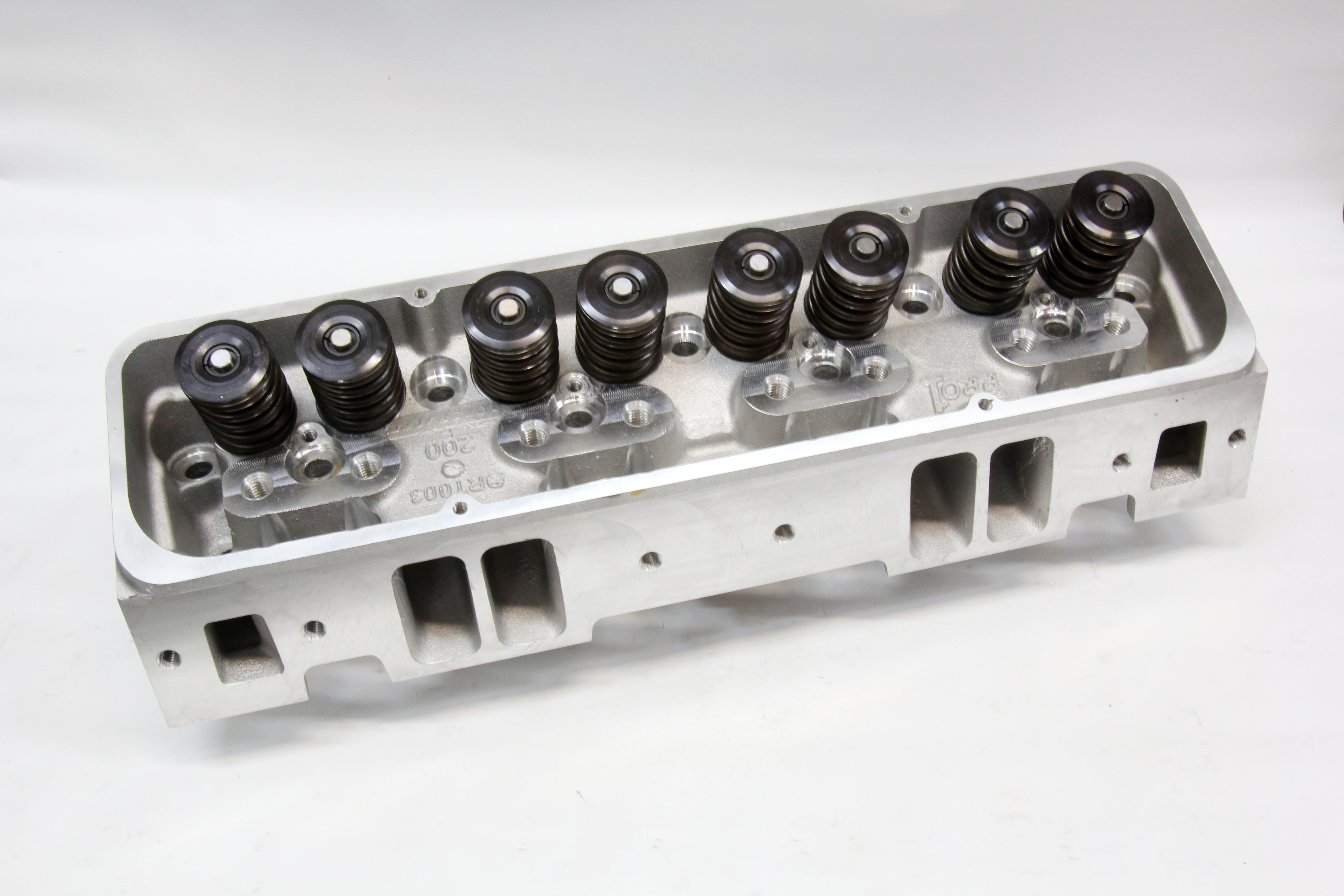
While many Dart cylinder heads come assembled with valve springs, sometimes it can be necessary to spec your own set that pair with your camshaft of choice. Here's how to correctly set up a cylinder head.
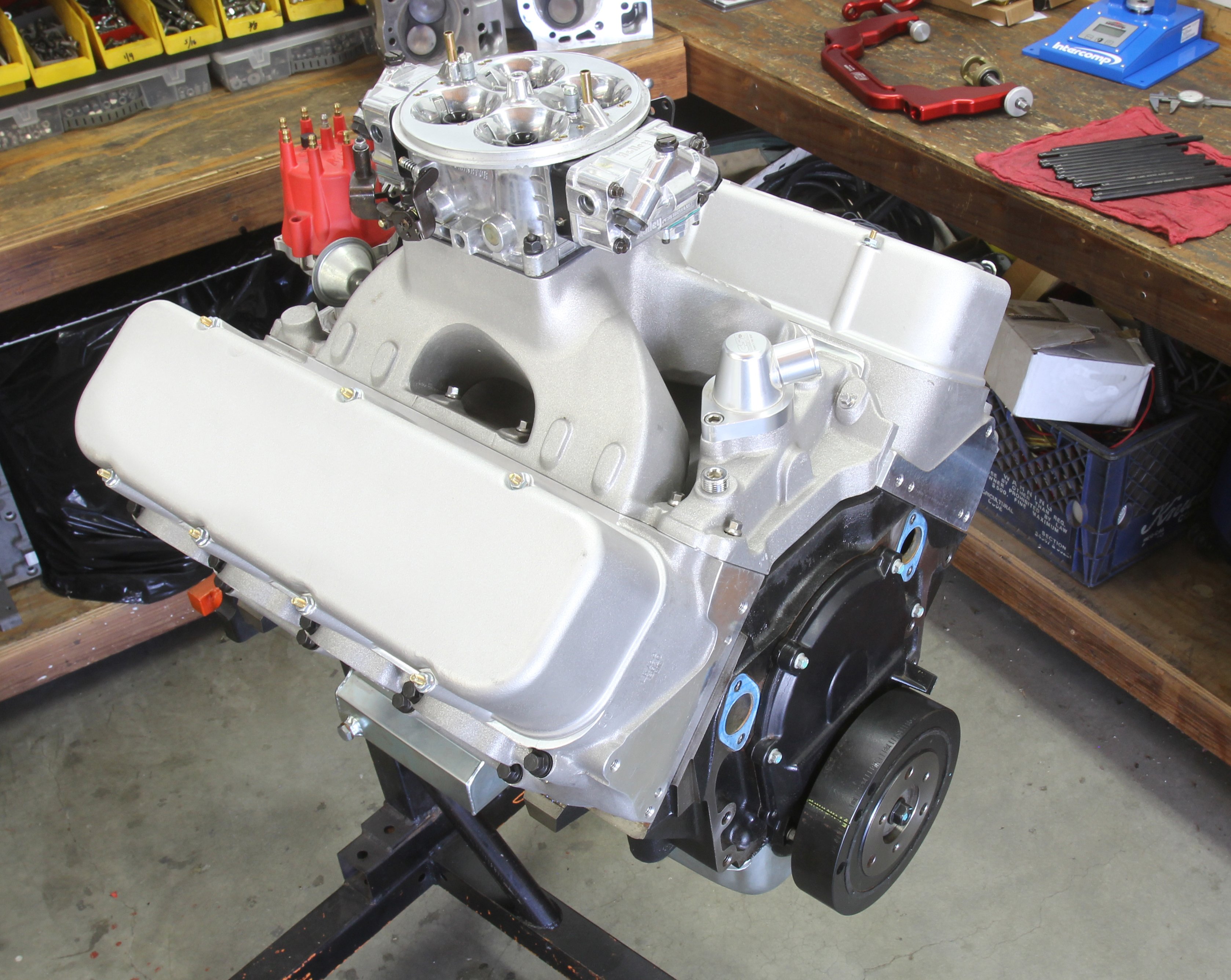
Building a unique performance engine often demands an equally custom set of heads. These cylinder heads may not fit within the confines of a specific off-the-shelf part number. Or, you may decide you’d like to assemble the heads yourself to create a specific combination for a race or street engine. With help from a few affordable tools, almost anyone can custom assemble a set of performance heads. We’ll show you how it’s done.
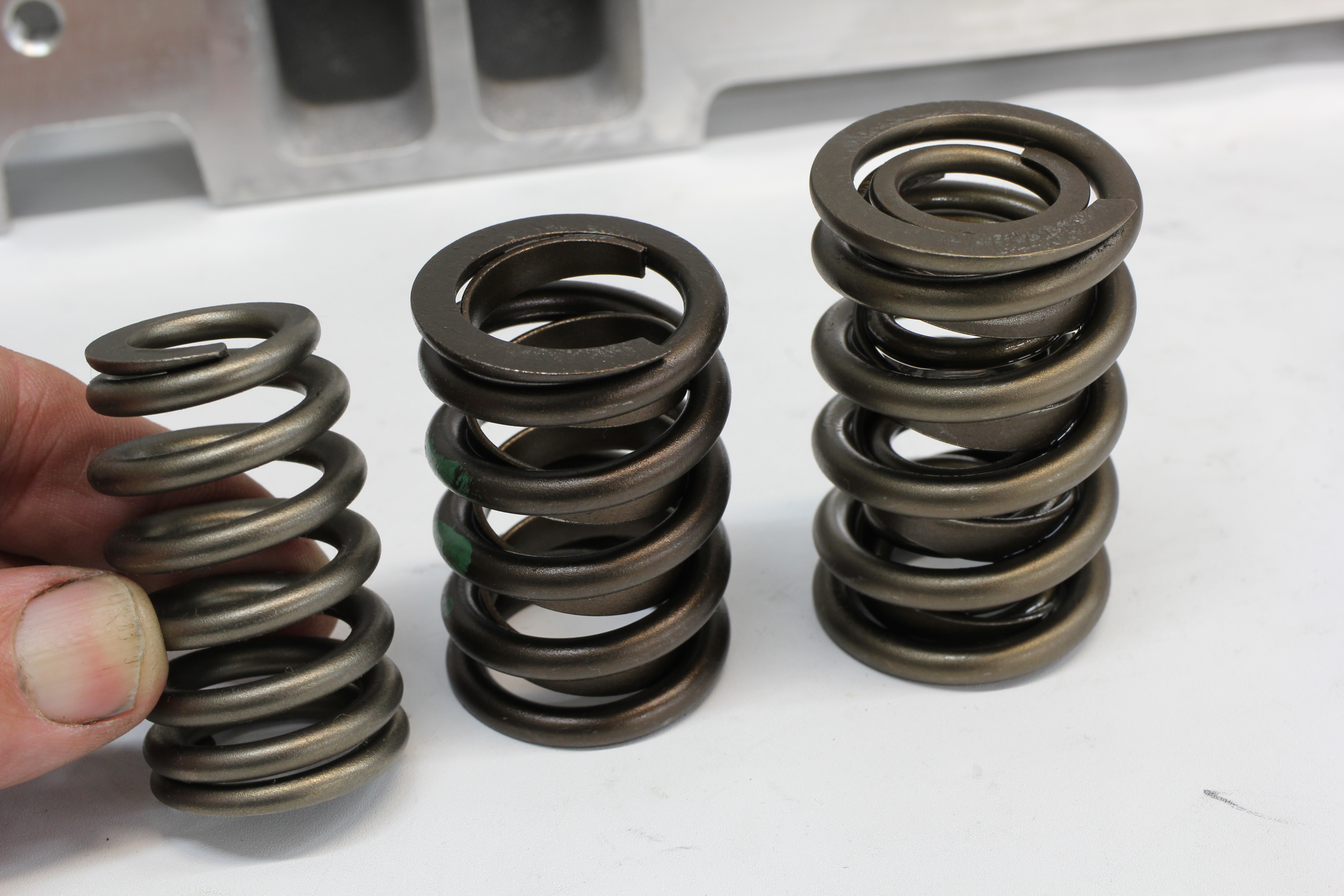
The most common situation for custom assembling heads would be to match a given set of valvesprings to a specific camshaft and valvetrain. The story of selecting valvesprings for a performance engine is far too complex to deal with here so we’ll assume you have already identified the valves and springs and all that’s left is to assemble all the pieces.
Blueprint Specs
Clearance Spec
- Coil Bind 0.050
- Retainer-to-seal 0.050
- Retainer to Rocker arm 0.050
- Roller Tip to Retainer 0.050
- Seal to spring clearance 0.050
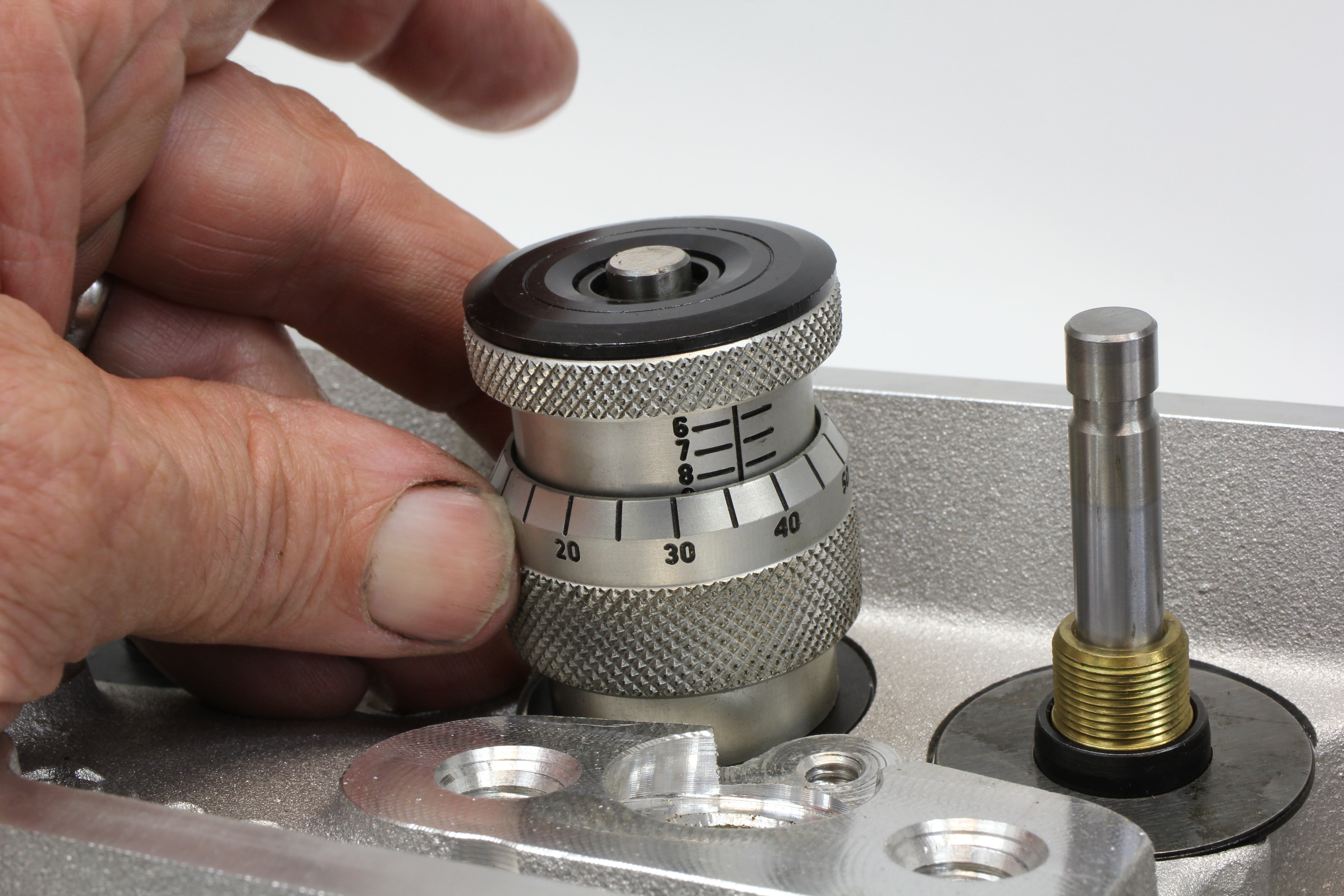
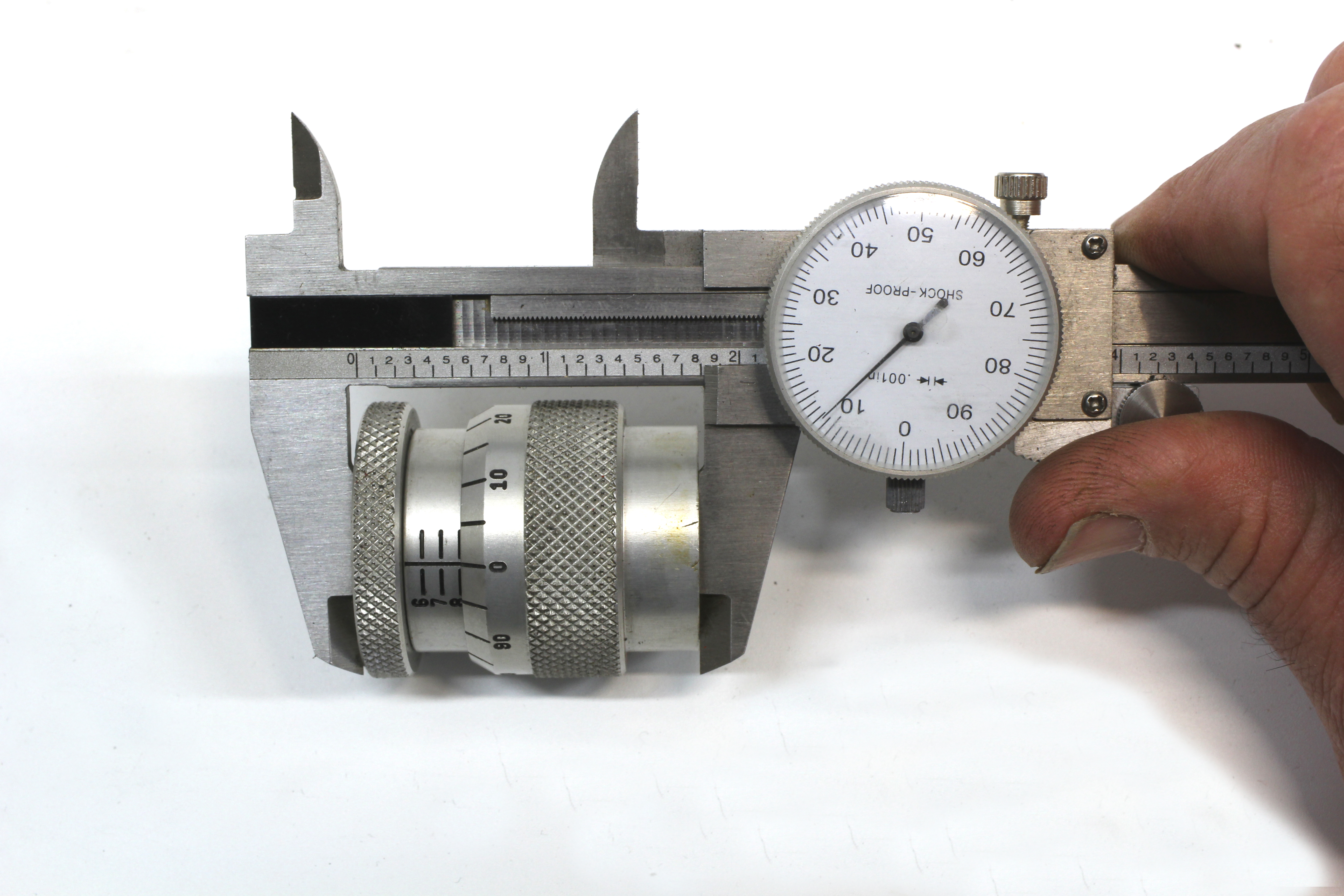
A great starting point is measuring installed height. This is the distance between the spring seat in the head and the bottom of the valve spring retainer. This dimension not only establishes the amount of load holding each valve closed but also affects the maximum valve lift spring load as well as affecting several other critical clearances. The easiest way to measure installed height is with what is called a height mic. Always measure the installed height using the spring seats (or locators) that will be used in the final assembly. There are a couple of other important specs you need to know before we can measure installed height.
It might be a good place here to mention the common practice of using taller intake valves. It’s not unusual now to see small- and big-block heads using 0.100-inch taller intake valves to accommodate increasingly taller valve lift numbers in the 0.600- to 0.700-inch range for aggressive small- and big-blocks.
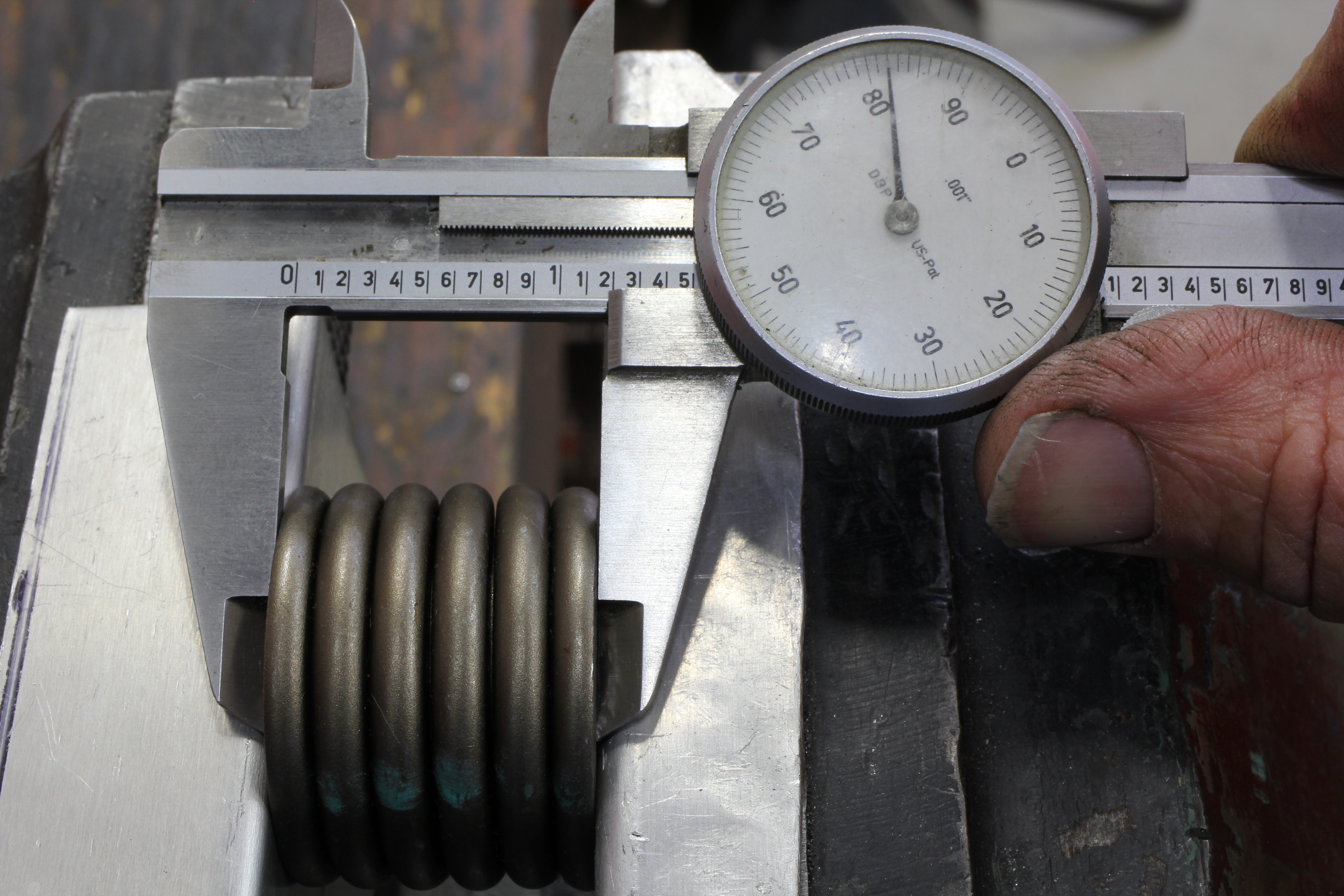
Part of the reason for choosing the correct spring also is tied to the spec referred to as coil bind. This is the height of the spring when fully collapsed. For obvious reasons, you need a spring that can accommodate maximum valve lift without fully collapsing. As an example, if we have a 0.650-inch peak valve lift and an installed height of 1.800-inch, peak lift will compress the spring to a height of 1.150-inch. This means this application will need a spring that will coil bind at 1.100-inch or less to have sufficient clearance.
This minimum clearance is generally recommended at 0.050-inch or roughly 0.010- to 0.012-inch between the spring’s moving coils. In the past, greater clearance was highly recommended, but current performance engine builders prefer a tighter clearance to coil bind as this helps dampen spring oscillation at high rpm which improves spring life and valve control. But this demands attention to detail.
All springs offer published coil bind specs, but actually measuring the spring reveals these published specs are often conservative. To be completely accurate you would need to measure all 16 springs to determine their individual coil bind specs and then set up the clearance to match the tallest spec. This is a lot more work, but also highly accurate.
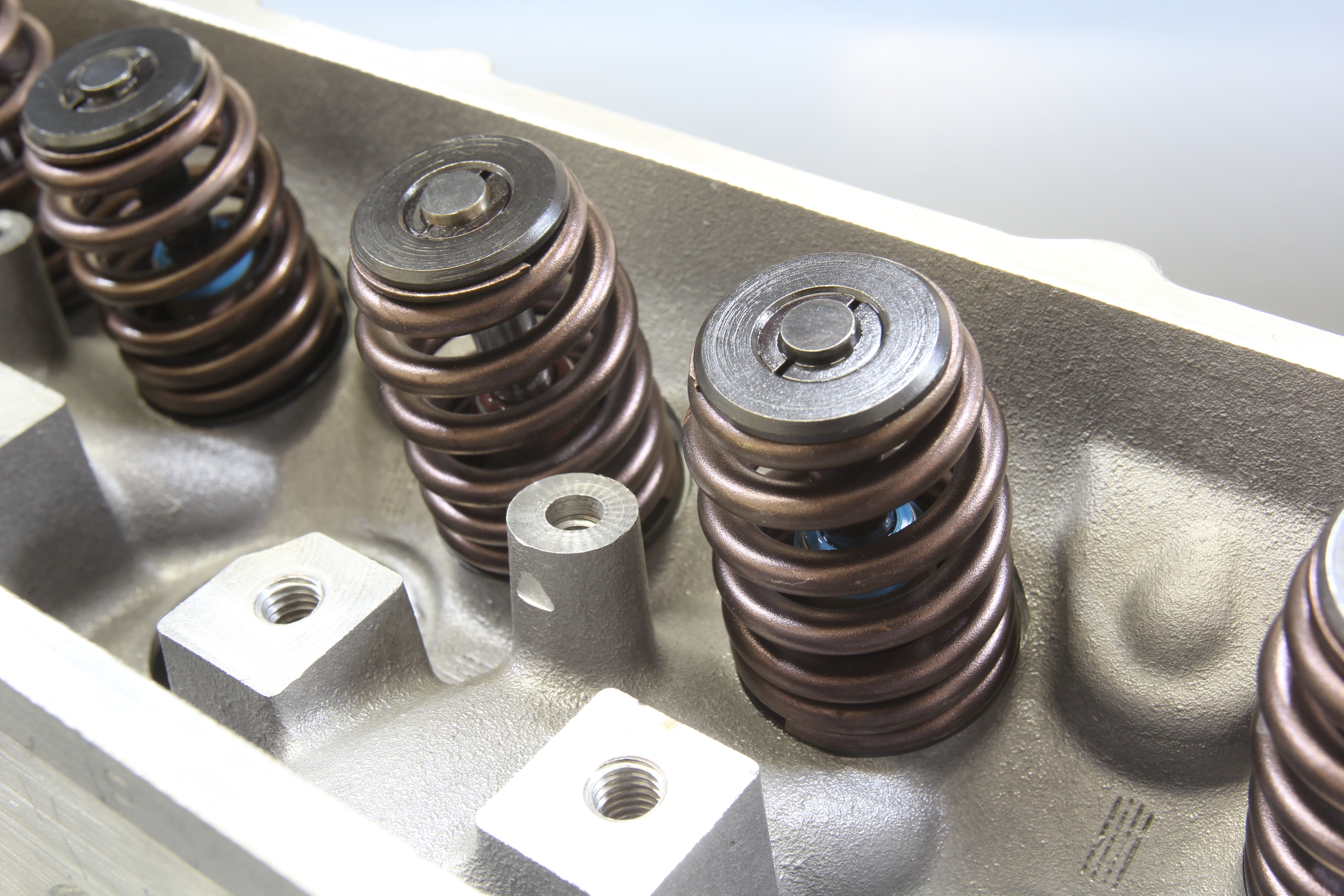
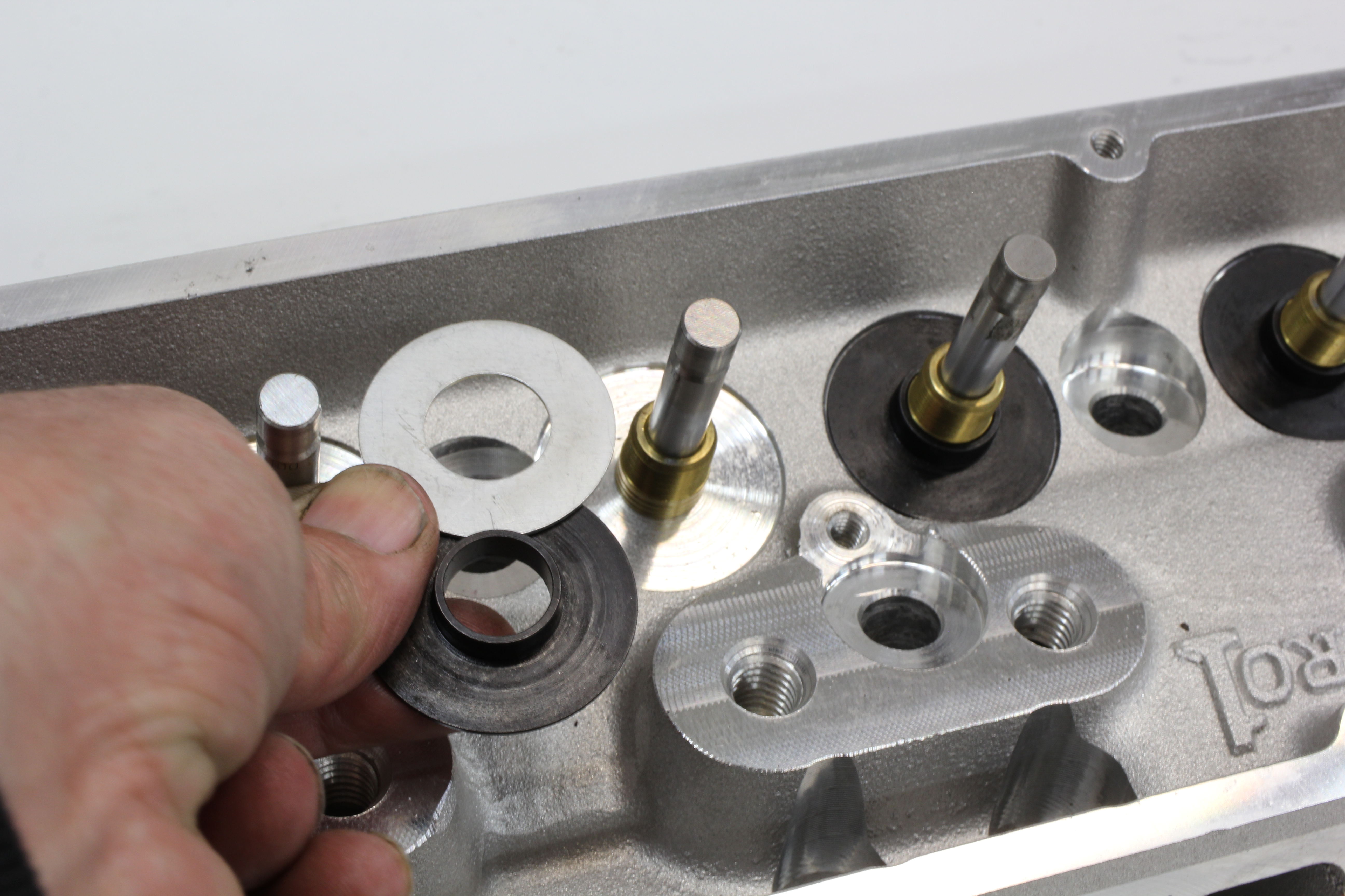
Spring seats – or spring locators are another part of the assembly puzzle. These pieces are designed to locate the bottom of the spring so it doesn’t move around. There are both inside and outside style seats. The outside design uses a ridge around the outer circumference while the more common inside or inboard style uses a step to locate the spring. Both work well so it is left to the assembler’s personal preferences. These seats come in specific diameters for the springs and can also be found in different thicknesses to help with establishing installed height.
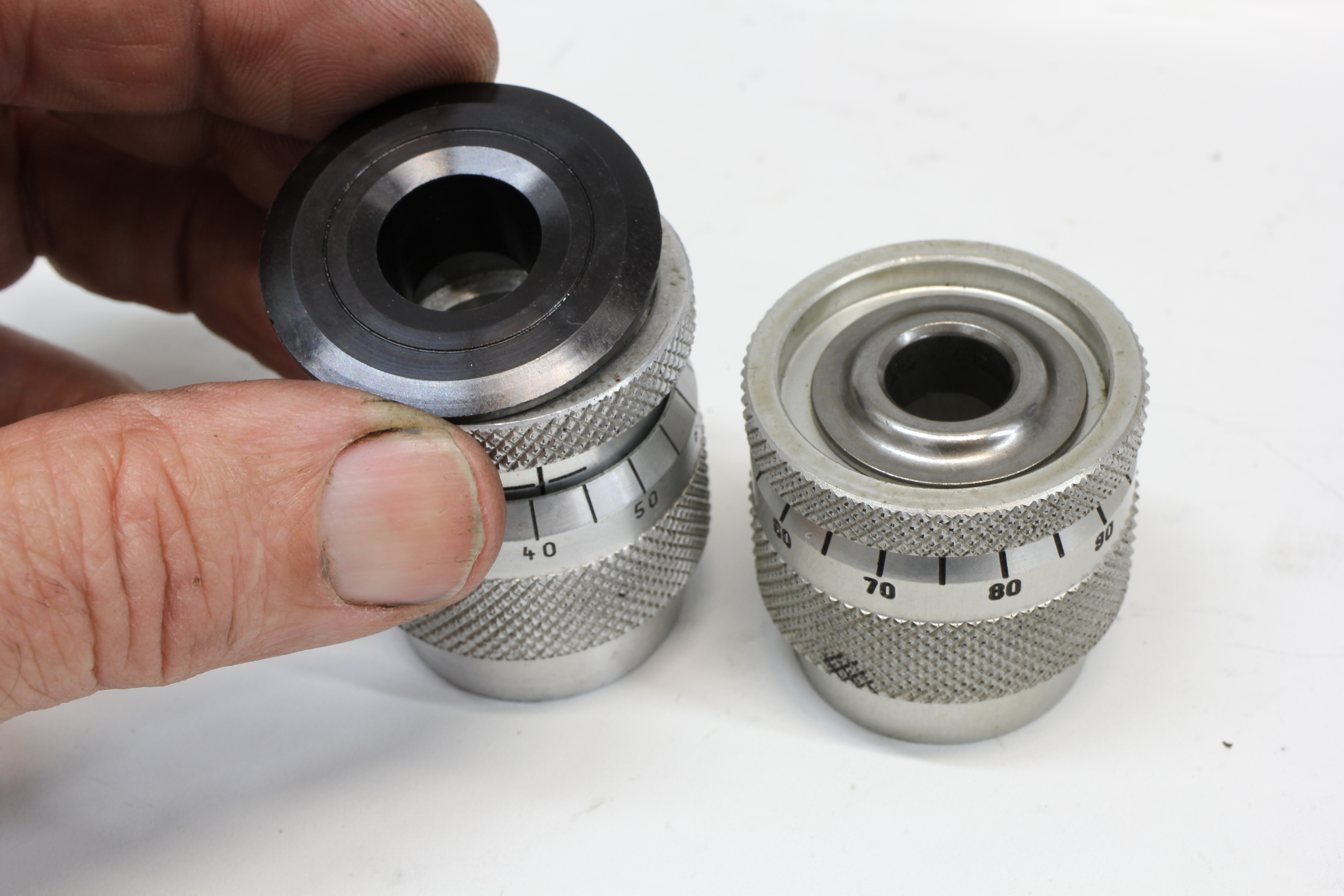
Installed height is easy to measure by setting up the mic underneath the retainer and locks for a given valve and then expanding the tool until it fits snugly between the retainer and spring seat. One thing to watch is that most height mics have a step in the top for smaller diameter retainers. If the retainer fits inside this step (as with LS engines or beehive springs), it’s necessary to subtract 0.100-inch (the depth of the step) from the mic’s readout.
All valve springs offer a specific load for the installed height. This is the amount of load that keeps the valve on the seat. For example a typical 1.4370-inch diameter dual valve spring will create a seat load of 130 lbs. with an installed height of 1.800-inch. Let’s say the spring has a rate of 400 lbs per inch. This means if the spring is compressed one inch, the load will increase by 400 lbs added to the load created from the installed (valve closed) position.
To determine the spring load at max lift, all we have to do is multiply the spring rate times the valve lift and add that to the installed height load. As an example, let’s say our cam produces a maximum lift of 0.600-inch. Multiply 0.600-inch lift x the 400 lbs/in gives us 240 pounds of load. Add that to the seat load of 130 lbs (240 + 130 = 370 lbs) and we have the load at maximum valve lift.
When checking installed height, most often you will find the measured height is 0.015 to 0.030-inch taller than the height you desire. The easiest way to idealize this height is to use valve spring shims. The most common thicknesses are 0.015-, 0.030-, and 0.060-inch and they can be combined to create the exact dimension required. It’s not essential to stress over the last 0.010-inch because on a 400 lb/in spring that represents a difference of only 4 lbs. You may notice that the shims are serrated on one side. These are always placed facing the head.
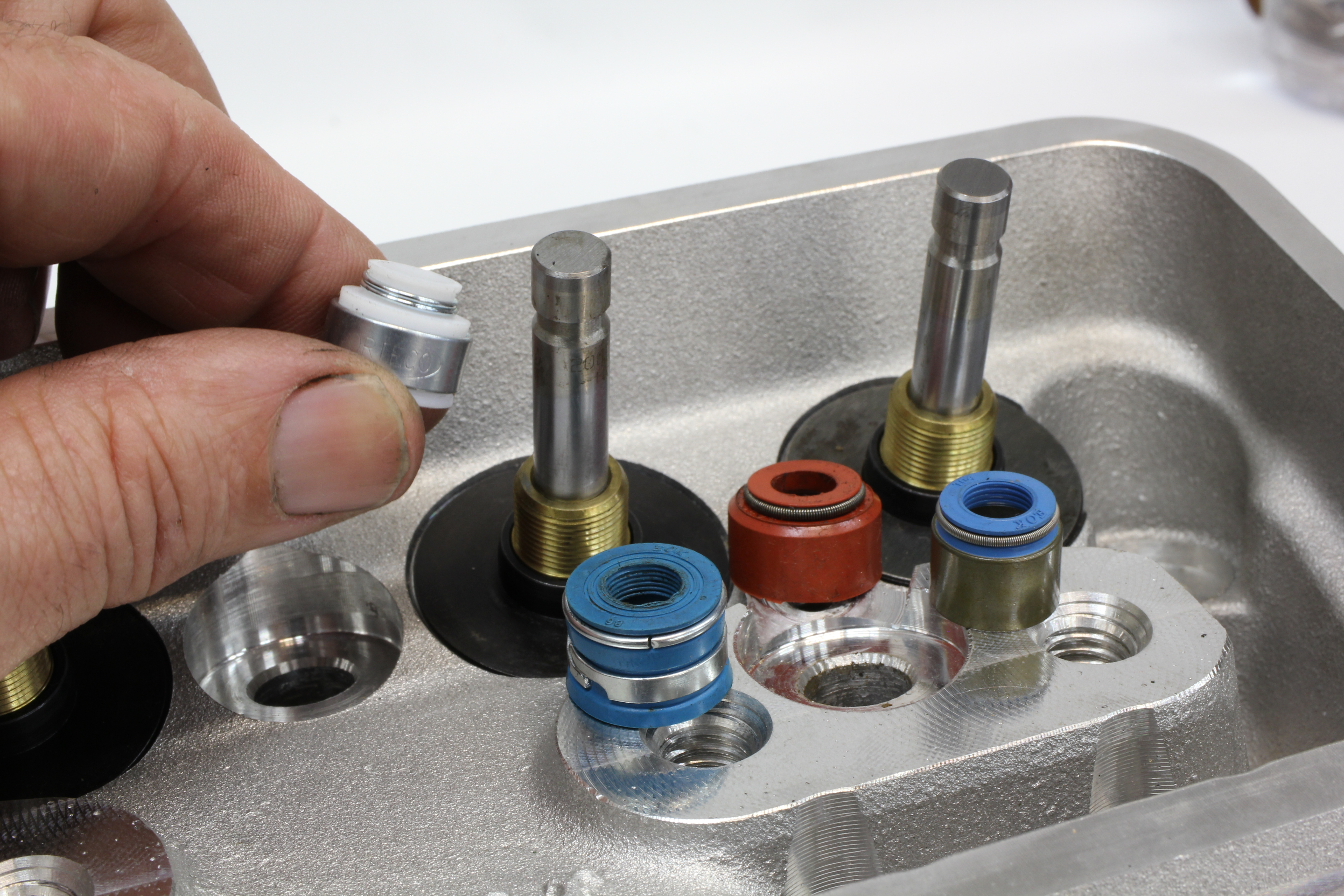
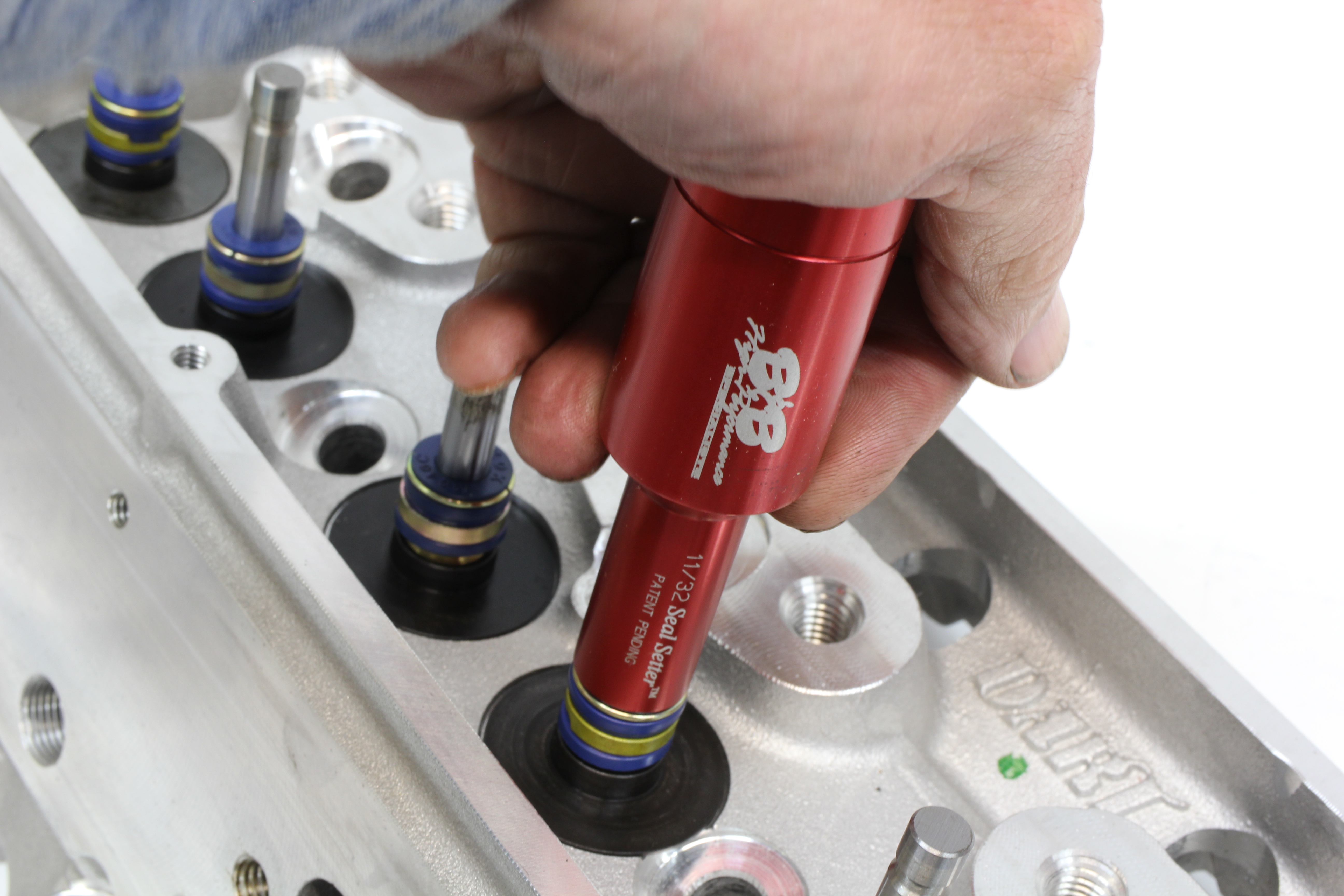
Assembling your own heads also allows you to choose the valve guide seal. It’s important when packing all the components to ensure that the seal will fit inside the spring. Sometimes with dual springs, the clearance between the inside spring and the seal can get tight. Another piece of the puzzle is the style of seal. Currently, the most popular seal is one that fits over the valve guide in the head and the most effective seals are the Viton rubber version. Ordering the correct seal means knowing the outside diameter of the valve guide as well as the valve stem diameter. The Viton rubber seals tend to work best on the street to help control oil compared to the harder plastic PC style seals.

Once the seals are installed over the guides you can measure the retainer-to-seal clearance. This is an important clearance to ensure the retainer does not hit the seal at or near max lift. The standard minimum clearance is 0.050-inch. Most performance heads are built with more than sufficient clearance. The one small-block head that has problems in this area is the iron Vortec head.
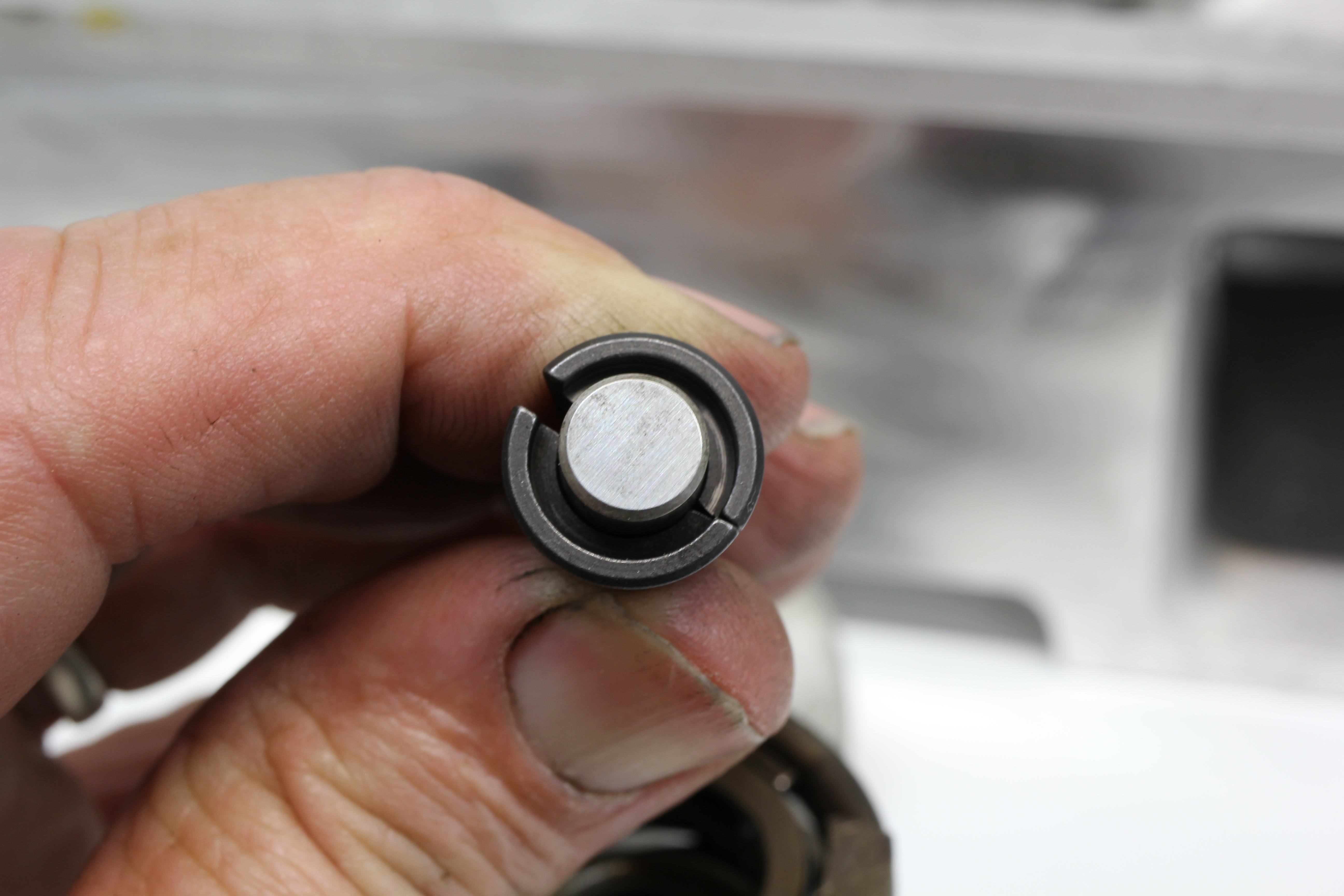
If you are assembling a set of heads from various components and manufacturers, it is best to ensure that the locks and retainers are compatible and that they are matched to the valves. Locks are intended for a specific valve diameter but can be improperly matched. Make sure the locks fit the valve properly. With the locks positioned around the valve, there should be a slight gap between the pair of locks. If both halves fully touch, the locks are incorrect for the valve and will fail almost immediately.
Many performance valvetrains are now using 10-degree locks instead of the more traditional and smaller 7-degree versions. The 10-degree style offes a larger surface area making it easier to disassemble but still must be matched both to the proper valve diameter and the retainer.
Most performance valves are machined for a single, square edge lock groove. Recently, however, some valve companies are modifying their race valves with a rounded or radial groove. These require dedicated locks and should never be installed with square cut locks as the two are not compatible. Many performance valves now come with a small radius in the square cut grooves but still retain the use of square cut valve locks, so be sure to verify the proper locks with the manufacturer. Locks are available in either stamped or the higher-quality machined versions.
During the checking procedure, you may discover the need to increase the installed height. While machining the spring seat is an option, this generally should be avoided because this can create a thin area near the roof of the intake port that can easily crack. A better option is to either use a thinner spring seat or relocating the valve locks. Dart, and other valvetrain companies offer valve locks that can raise or lower the position of the retainer on the valve.
When using + 0.050-inch locks, the retainer moves closer to the end of the valve. This reduces the clearance between the roller rocker tip and the retainer. There needs to be a minimum of 0.050-inch vertical clearance between the valve tip and the top of the retainer.
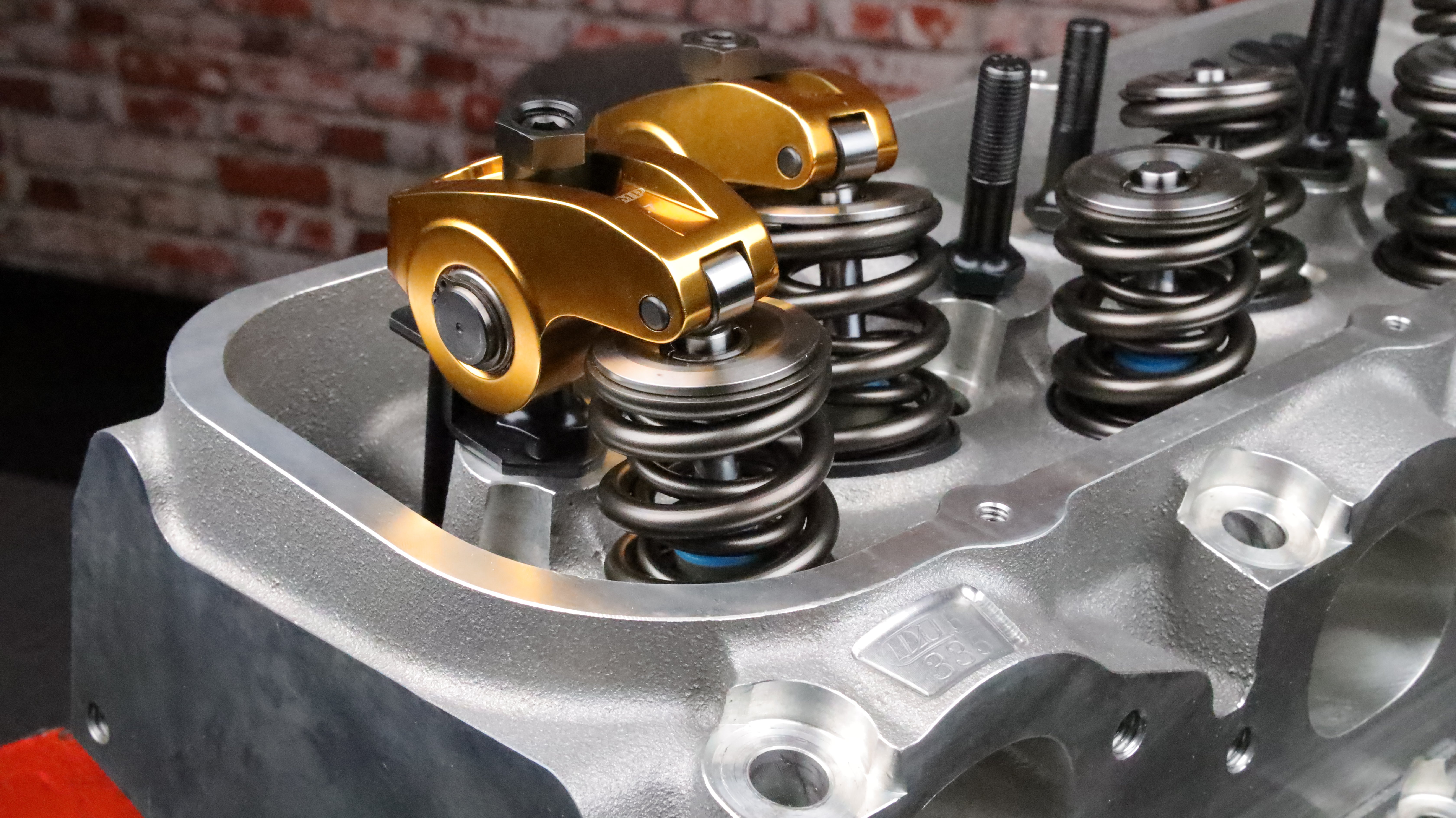
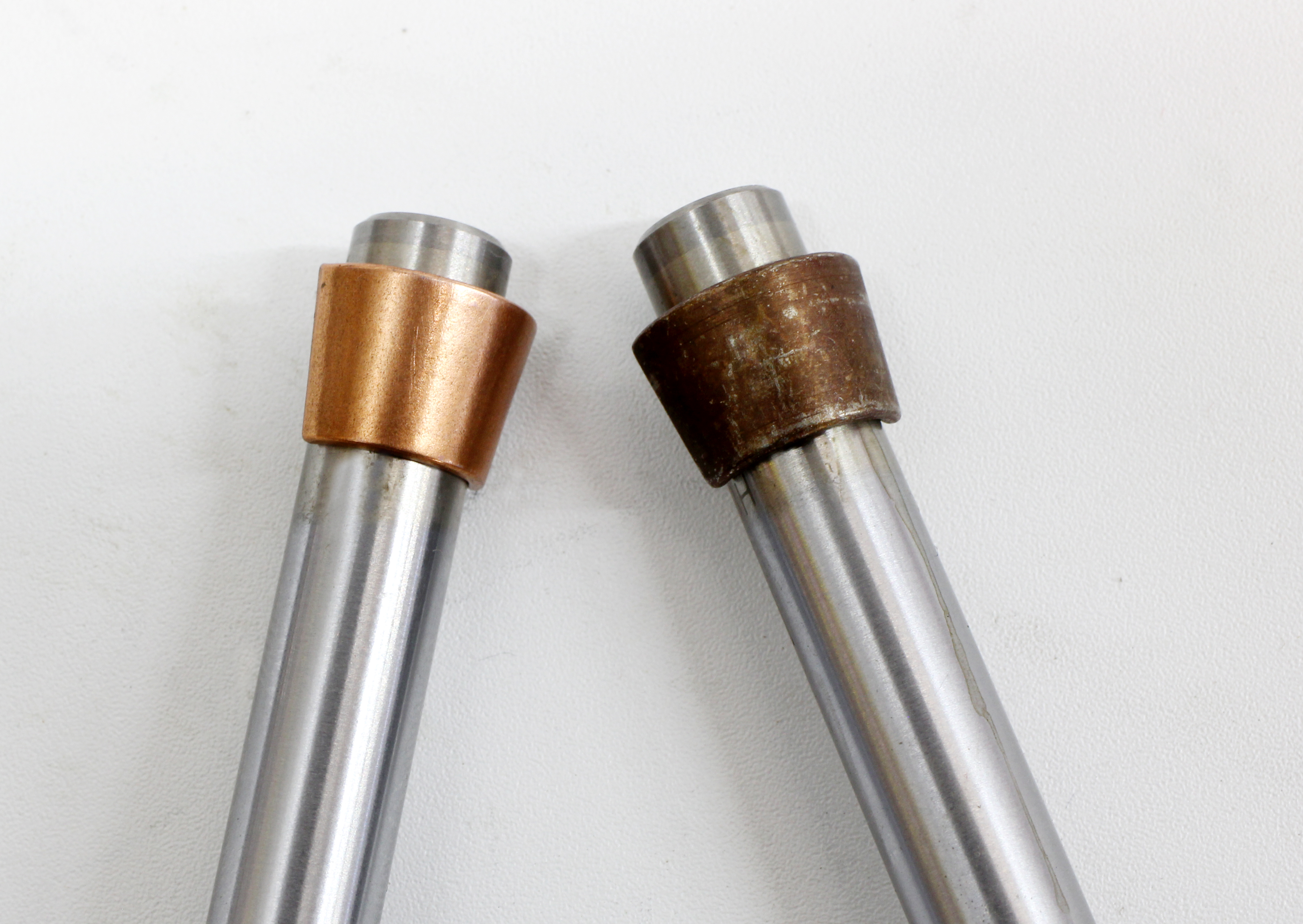
Raising the retainer height will also affect retainer clearance to the rocker arm. Rockers most susceptible to this are the large body aluminum rockers that may not offer sufficient clearance underneath to rocker’s tip length. This clearance also needs to be a minimum of 0.050-inch. Both of these clearance issues can be solved with the use of a lash cap over the end of the valve. This lash cap, along with a longer pushrod can potentially solve these issues, but this gets into the myriad of details involved with engine valvetrain blueprinting that we will save for a separate story.
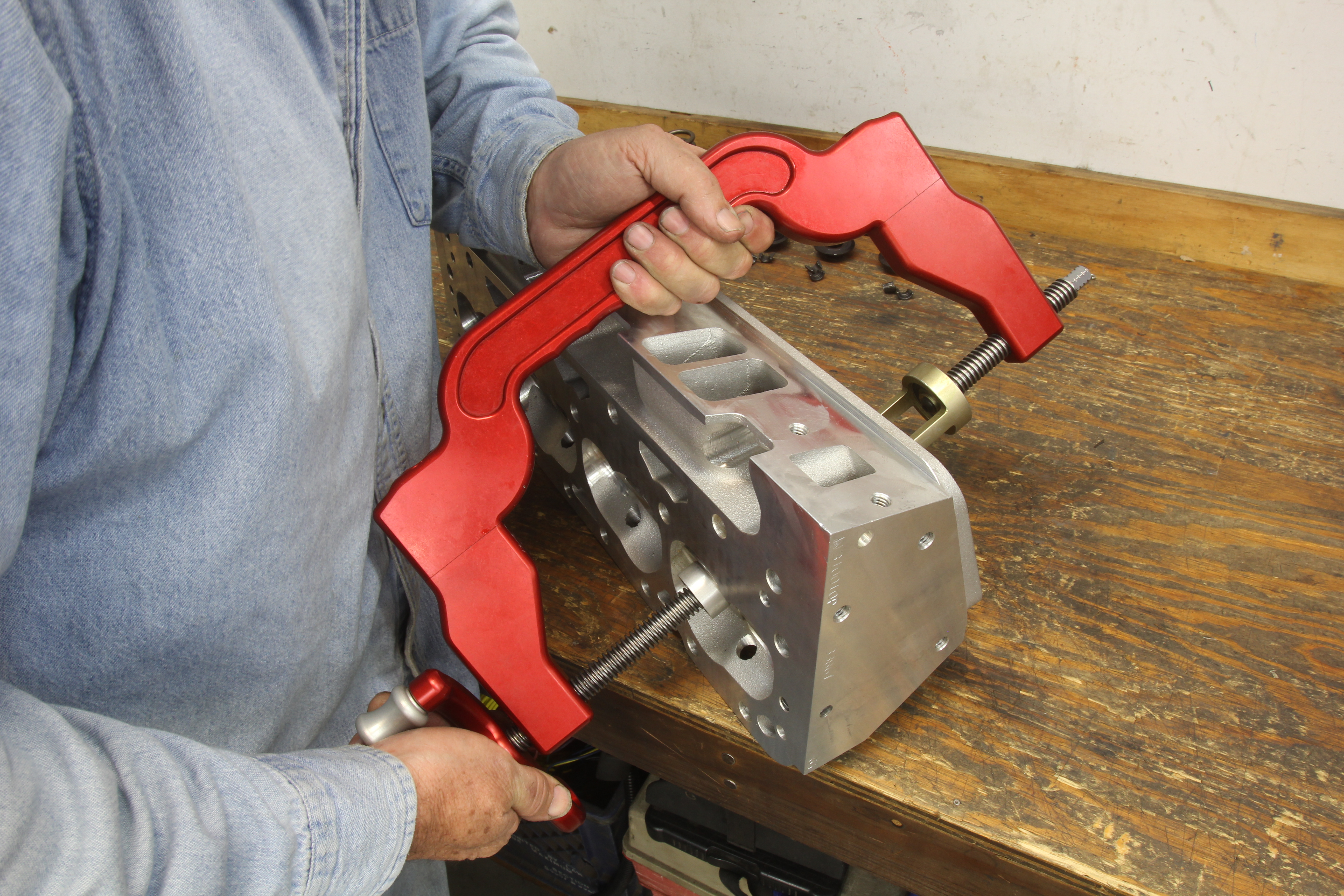
Final valve spring assembly should include coating the valve stems with a quality assembly lube and then carefully installing the valve stem seals over the guides. With the shims in place, the springs can be installed with a quality valve spring compressor. Final assembly of the rocker studs and pushrod guide plates (if used) should wait until the heads are torqued in place on the engine. Dart offers adjustable guide plates for both small- and big-block Chevys that are helpful in final alignment of the rockers over the valve stem tips.
As performance engines become increasingly aggressive, especially with high-lift camshafts and stratospheric engine speed limits, the demand for a properly assembled set of heads will also continue to escalate. Proper assembly of a set of heads goes a long way toward building an engine that will withstand the repeated performance use abuse without complaint.